Research
Techniques & Modeling
GPS
The Global Positioning System consists of 24 satellites in 6 orbital planes around the Earth, a ground-based tracking network to determine accurate orbital information for the satellites, an uplink system to monitor satellite health, and occasionally send orbit and time corrections to the satellites, and a ground-based receiver capable of decoding the GPS timing/ranging signals to determine the user’s position. The main signal is called the C/A code (for Clear/Acquisition), modulated onto one of the two sinusoidal carrier signals (L1, L2) broadcast by the spacecraft. The C/A code has a wavelength of about 10 meters. The L1 and L2 frequencies have wavelengths of 20 and 24 centimeters.
The small hand-held systems most people are familiar with use the C/A code to determine range (distance) to several satellites. This is done by measuring a time offset (T) between the signal’s broadcast time at the satellite and reception on the ground. Knowing the speed of light (S) the receiver can then determine distance, D (D=S x T). A minimum of 4 satellites is required to determine the three position coordinates (x, y, z, or North, East, Up) and a parameter that relates to possible timing errors (four data, four unknowns). Boaters can get by with three satellites, since they do not require the vertical coordinate. Typical position uncertainties are of the order of several meters, limited in part by the wavelength of the C/A code.
For high precision geodesy, several modifications to this system are required. First, we use receivers capable of exploiting both carrier frequencies, to correct for variable ionospheric delay. The ionosphere speeds up or slows down the GPS signal (depending on the number and distribution of free electrons in the ionosphere), introducing errors into our basic range equation (by changing S). Fortunately, ionospheric effects are frequency-dispersive (different frequencies are delayed by different amounts), so use of two frequencies allows a first order correction. Second, in addition to using the C/A code, we also use phase measurements on the carrier itself. These are inherently more precise because of the smaller wavelengths involved. Third, instead of observing for a few seconds, we often observe for several hours or days, averaging down some of the position errors. Finally, instead of having a small, hand-held receiver compute a simplified position estimate, we use modern, high speed computers to determine a number of corrections that could be ignored at the meter level, but become important at the centimeter or millimeter level. These corrections often involve sophisticated models of Earth’s surface changes, related to tides, changes in the Earth’s rotation rate and rotation pole position, and seasonal changes in atmospheric pressure and rainfall.
InSAR
Synthetic Aperture Radar (SAR) is a powerful remote sensing system, enabling observations of the Earth’s surface day or night, in all weather conditions from airborne platforms and from space. Unlike optical remote sensing systems, which rely on the Sun for illumination, SAR provides its own, illumination via microwave (Radar frequency) transmissions from the satellite. These transmissions are coherent, meaning that both amplitude and phase information are retained. The Sun’s illumination reaching the Earth is incoherent (scrambled), meaning that only amplitude information can be used. This leads to another important difference between optical and SAR systems. In many cases, the coherent phase information transmitted by a SAR satellite or aircraft is reflected from the surface back to the sensor with the phase more or less intact. A subsequent satellite pass, several days to several years after the initial pass, may also retain the phase information. A phase comparison of the two images via interferometric techniques may reveal subtle shifts in the position of the Earth’s surface (closer to or farther from the satellite). This technique is known as Interferometrtic SAR (InSAR). It can be done from either aircraft or spacecraft, but for most scientific applications, space-based platforms are preffered.
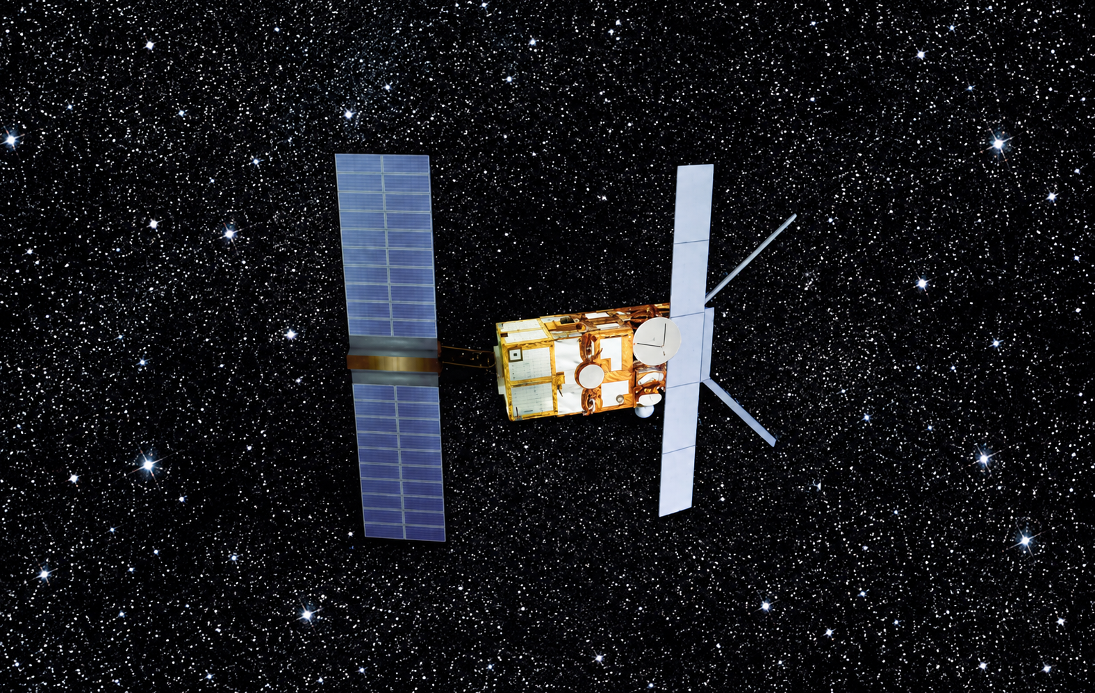
Figure 1. Sketch of the ERS-2 satellite, a primary source of SAR data for many scientific investigations. Note the large array of solar panels on the left, necessary to supply power to this active imaging system. The large panel on the right is the SAR antenna, which has the dual role of illuminating the Earth's surface with microwave energy, and receiving the resulting backscattered signal.
The potential precision of InSAR depends on many things (e.g., the accuracy of the orbit determination for the two satellites passes, atmospheric conditions that affect the phase delay) but in principle the surface displacement measurement can have a precision of 2-5 % of the SAR wavelength. Typical SAR wavelengths are in the range 3-30 cm, implying millimeter to centimeter precision in surface displacement between two satellite passes. Refinements of this basic technique include “stacking” of multiple SAR passes to reduce noise. InSAR has been used to study co-seismic offsets due to earthquakes, volcano deformation, and subsidence due to withdrawal of ground water, oil, or natural gas (see reviews by Massonett and Feigl, 1998, and Rosen et al, 2000).
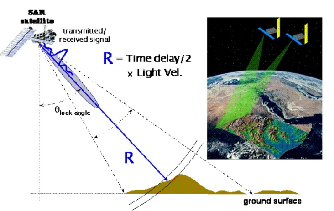
Figure 2. illustrating some of the basic principles of SAR interferometry. The right hand inset show two satellites illuminating the same region of the Earth. In practice, a single satellite illuminates the area, followed several weeks to years later with a second image from the same satellite in the same nominal orbit. Displacement of the Earth's surface between the two successive satellite passes is estimated, following principles illustrated in the left hand side of the figure.
The two basic requirements are that the orbits of both satellite passes are known precisely, and that the phase information inherent in the SAR signal is exploited (electro-optical satellites, using the visible and infra-red portion of the electomagnetic spectrum, utilize only amplitude information; SAR uses both amplitude and phase). Then phase information from the two satellite passes (each of which in effect is a type of distance measurement) is used to estimate the change in distance (range change) between the two passes, in the direction of the satellite line of site ("look angle"). This means that the measurement is inherently scalar. The use of both ascending and descending passes can be used to determine a two dimensional vector measurement.
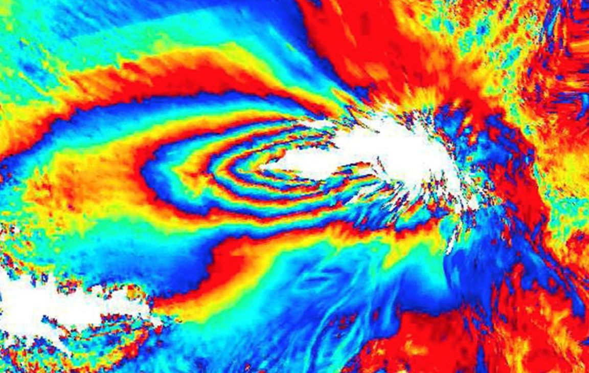
Figure 3. Interferogram from Tungaraghua volcano in Ecuador
Permanent Scatterer InSAR
While InSAR is a powerful technique for measuring changes in the Earth’s surface, it does have limitations. These include temporal and geometrical decorrelation (low signal to noise ratio in the phase change estimate), and variable tropospheric water vapor, which can generate variable phase delay due to the impact of water vapor on the propagation speed of microwave signals. The corresponding phase changes can be misinterpreted as surface change. The effects can be quite large, especially in tropical and sub-tropical regions. In tropical regions, up to 10 cm of variable path delay over several weeks has been observed [Dixon and Kornreich-Wolfe, 1990; Dixon et al., 1991]. An example of a tropospheric water vapor “signal” in a SAR interferogram in sub-tropical New Orleans is shown in Figure 4. Although the water vapor signal is only about 6 mm, the passes are separated by just 3 weeks, implying an annual average subsidence rate in excess of 100 mm/yr. The average subsidence rate here is known to be about 6 mm/yr, so clearly the tropospheric error can be significant.
Permanent Scatterer InSAR (PSInSAR) [Ferretti et al., 2000, 2001;2004; Colesanti et al., 2003a,b,c] exploits several characteristics of radar scattering and atmospheric decorrelation to measure surface displacement in otherwise non-optimum conditions. Atmospheric phase contributions are spatially correlated within a single SAR scene, but tend to be uncorrelated on time scales of days to weeks. Conversely, surface motion is usually strongly correlated in time. An example is surface subsidence, which is usually steady over periods of months and sometimes years. Thus, atmospheric effects can be estimated and removed by combining data from long time series of SAR images, averaging out the temporal fluctuations. Radar scatterers that are only slightly affected by temporal and geometrical decorrelation are used, allowing exploitation of all available images regardless of imaging geometry. In this sense the scatterers are “permanent”, i.e., persistent over many satellite revolutions (the technique is also known as Persistent Scatterer InSAR).
What constitutes a permanent or persistent scatterer? Man made structures in urban settings are most common. Inspection of the individual scatterers in a PSInSAR image of New Orleans indicates that many of the scatterers are located at the intersection of a street or sidewalk and vertical structure such as the side of a building, or a roof (Figure 5). In contrast, parks and other vegetated areas have no permanent scatterers, presumably because vegetation is not a strong radar reflector, and also undergoes significant wind-driven motion as well as growth over the imaging period (in this case, three years). This implies that the PSInSAR technique is ideally suited to studying surface changes in urban areas, e.g., due to subsidence or co-seismic offsets.
We used the PSInSAR technique to study subsidence in New Orleans [Dixon et al., 2006]. We used 33 RADARSAT (6 cm wavelength) scenes acquired between April 2002 and July 2005 in the ascending orbit, standard beam mode (S-2). A total of more than 1.8x10⁵ radar targets were identified that retained some phase coherence over the three year study period, providing excellent spatial resolution for our space-derived surface velocity map (Figure 6). Both InSAR and PSInSAR are by definition relative (ambiguous), hence determination of the actual subsidence rate requires calibration with one or more ground control points of known elevation and motion. This is usually accomplished by referencing to stable areas ~50 km away from the locus of deformation, where motions are assumed to be minimal. This is problematic in the Gulf coast, where a large region is thought to be subsiding. We use a ten year time series from a high precision GPS station in the greater New Orleans area (ENG1) to provide an independent reference.
The mean and standard deviation range change rate for all the point targets is -5.6±2.5 mm/yr. The range change measurement is in the radar line of site direction, but can be considered nearly equivalent to vertical subsidence. The inset to Figure 6 shows an expanded view of one of the levees in the eastern part of New Orleans that failed during Hurricane Katrina (Figure 7). These levees have high subsidence rates (in excess of 20 mm/yr) and there may be a relation between high subsidence rates and levee failure, e.g, the underlying substrate may be weak.
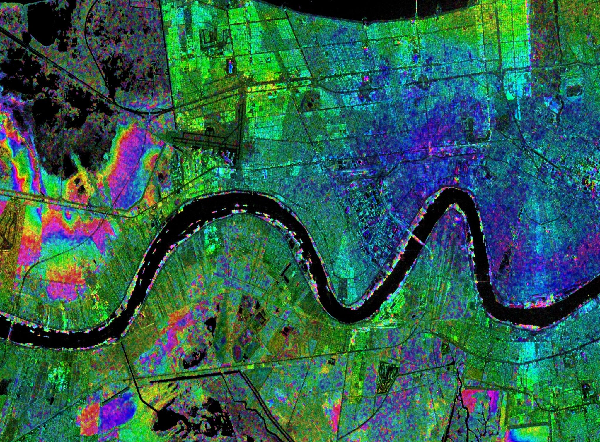
Figure 4. Synthetic Aperture Radar (SAR) interferogram superimposed on a SAR amplitude image of the greater New Orleans area and Mississippi River.
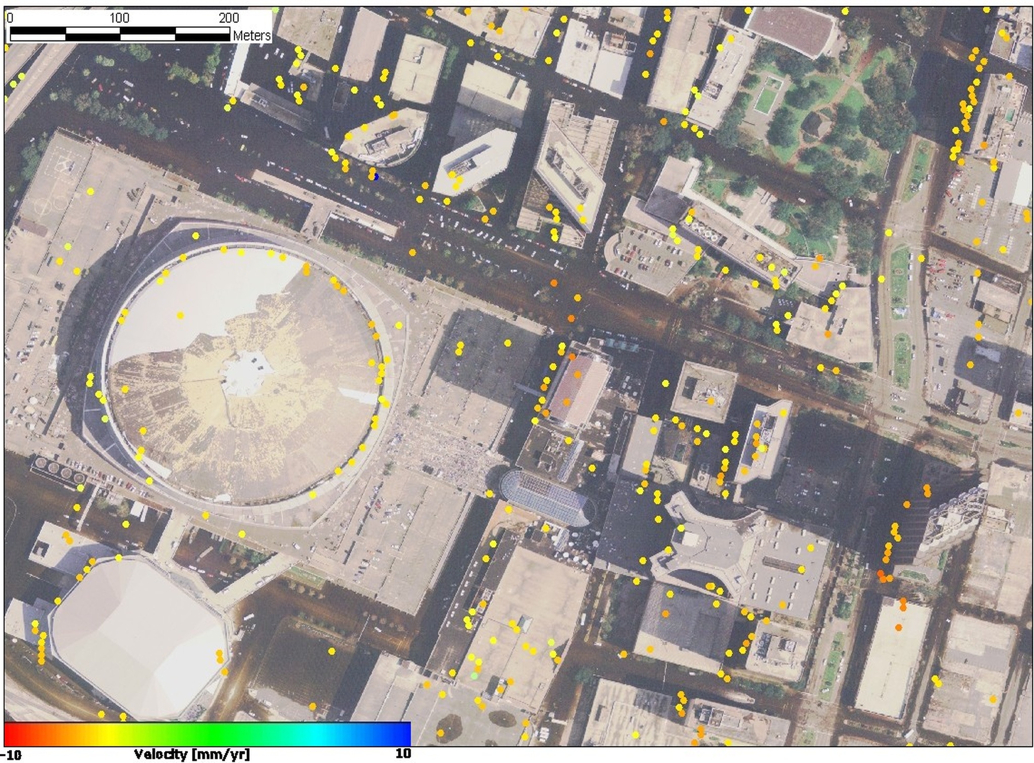
Figure 5. Close up of Superdome near downtown New Orleans from aerial photography after Hurricane Katrina (note damaged roof of Superdome), with superimposed velocity of permanent scatterers. Radar illumination from left, solar illumination from right.
The interferogram above from fig 4 represents phase changes in two SAR images between February 5 and March 1, 2005, , reflecting the 24-day repeat cycle of the satellite orbit. One color cycle (red-yellow-green-blue) in the interferogram represents 28-mm of range change between the ground surface and the radar antenna. Color changes on the west (left) side of the image represent level changes spanning 24 days southwest of the airport. The magenta pattern near the center of image could reflect soil moisture-related land subsidence, or more likely atmospheric effects over the same time period. These and other studies were discussed in sessions G14A and G23A (Hydrology from Space) and G43A (Subsidence of South-Central North America) at the Spring 2005 meeting of the American Geophysical Union, held in New Orleans. Radarsat data courtesy of the Canadian Space Agency, distributed by Radarsat International. Data were downloaded and processed at CSTARS (Center for Southeastern Tropical Remote Sensing), University of Miami. Interferometric processing by S. Kim, University of Miami.
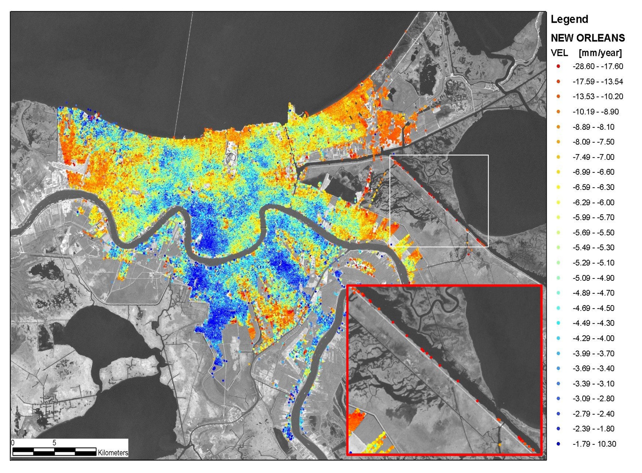 Figure 6. Velocity map for permanent scatterers in New Orleans and vicinity. Values
are range change in direction of radar illumination. Negative values indicate motion
away from satellite, consistent with subsidence. Int. Airpt. is location of International
Airport, MRGO is Mississippi River-Gulf Outlet Canal. Inset (location marked by white
rectangle) shows close up of PS velocity map for eastern St Bernard’s parish and western
Lake Borgne. Note high rates of subsidence on levee bounding MRGO Canal. Large sections
of the MRGO levee were breached during Hurricane Katrina in August 29, 2005. From
Dixon et al. [2006].
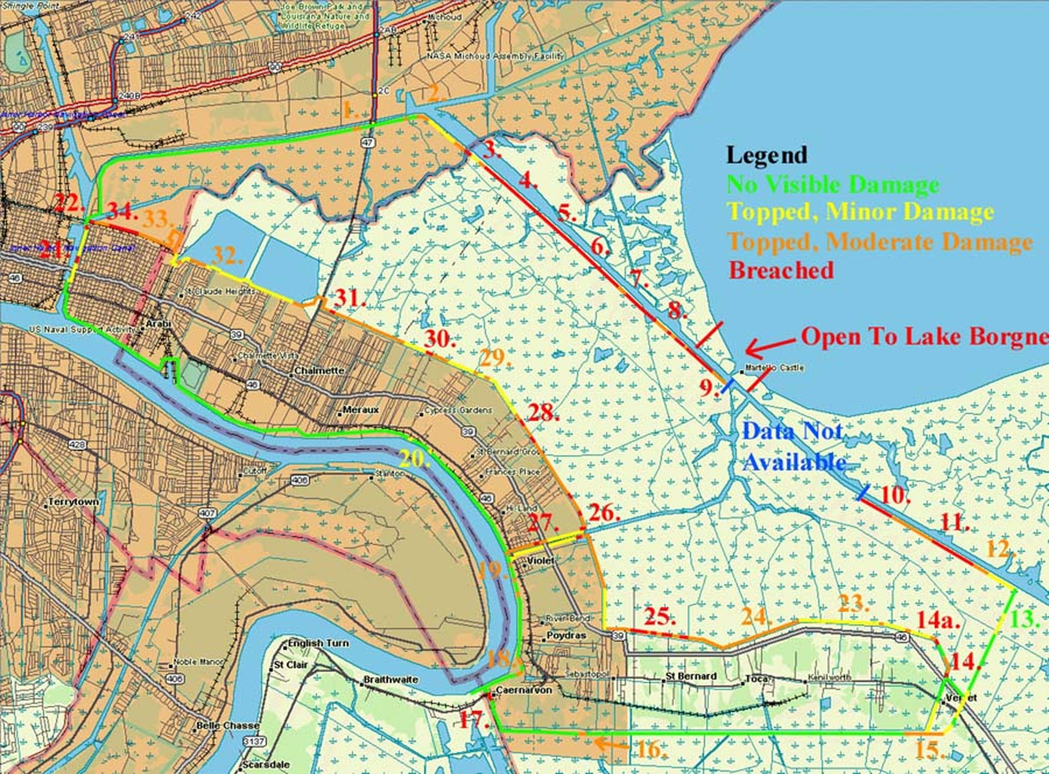 Figure 7. Map of breached levees in St Bernard Parish, from Free Republic. Note breached
levees along MRGO (points 3-9), corresponding to radar scatterers with high subsidence
rates.
Ground-based radar
Ground-based interferometry has several advantages over satellite interferometry. Using ground-based radar alleviates the problems associated with long revisit times, atmospheric effects, and the lack of densely-sampled data. The USF Geodesy Laboratory is in the process of obtaining a GAMMA Portable Radar Interferometer (GPRI). The GPRI is a real-aperture radar that operates at a frequency of 17.2 GHz (Ku-band) and allows for millimeter precision. The device consists of one transmitting antenna and two receiving antennas. Since the receiving antennas have a small separation distance between them, the signals received at each one can be combined to generate an interferogram. The GPRI is also portable and easy to set up and is able to collect a number of images in an hour (as opposed to several days or longer for InSAR), opening up new, frequent, and precise measurement possibilities not previously possible with satellite interferometry.
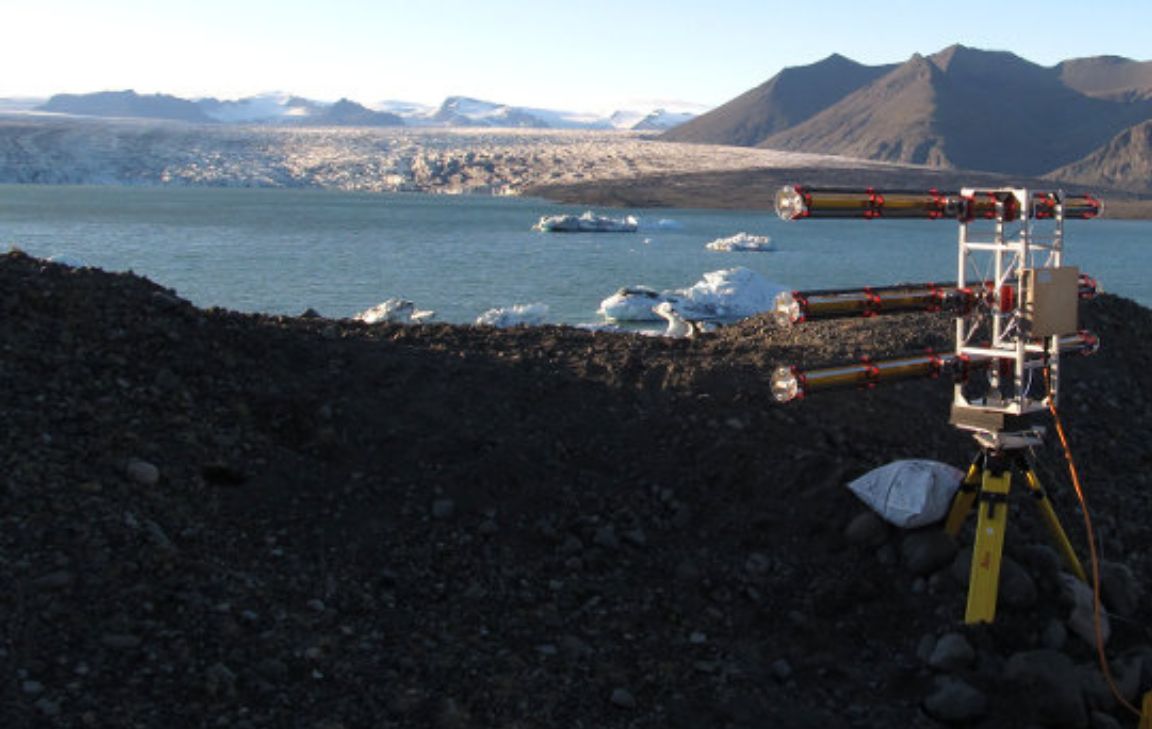
Figure 8.The GAMMA Portable Radar Interferometer (GPRI)
Volcano deformation
GPS and InSAR can be used to monitor volcano deformation. This is of great practical interest for hazard assessment, because volcanoes are thought to undergo significant inflation in the weeks or months prior to large eruptions (of course the data have to be available in a timely manner) [Dixon et al., 1993, 1995; Webb et al., 1995; Hagerty et al., 1997]. Volcano deformation is also of scientific interest, because the pattern and magnitude of surface displacement can be used to determine the depth, and in some cases the size and shape of the center of deformation, which may be related to the top of the magma chamber or a dike [Dixon et al., 1997; Mattioli et al., 1998; Newman et al., 2001, 2006; Walters and Amelung, 2005].
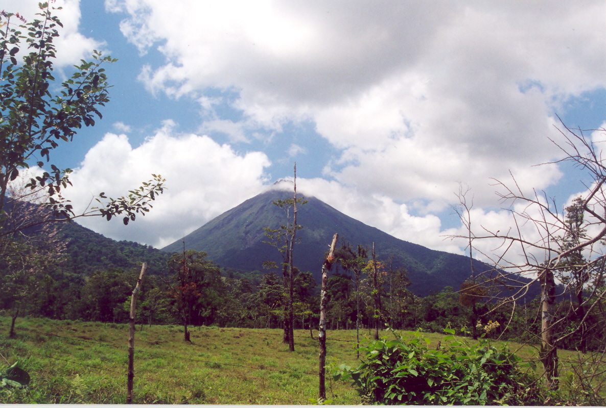 Figure 9. The Arenal Volcano in Costa Rica is a site of ongoing research.
Modeling
A standard procedure in most scientific studies is to compare data to a simplified model that captures most of the relevant physics of the problem. In this way we can use the data to test our understanding of the problem. In geodesy, we often assume a simplified rheology for the Earth’s crust and/or upper mantle, and compute the surface displacements that would be observed for a given condition (e.g., slip during and earthquake, or interseismic displacement or velocity associated with a fault’s long term, steady state rate of motion). The computed and observed displacements are compared, and if the fit is poor, one or more parameters of the model are adjusted to improve the fit of the model to the data. A minimum misfit model then gives an estimate of the optimum value for the adjusted parameters.
A standard rheological model for studying surface deformation associated with faulting, earthquakes, and volcano deformation is the elastic half space model. While this model does not reflect the ductile conditions known to occur at depth, it does a remarkably good job of matching a wide variety of geodetic data, presumably because the surface deformation field is mainly sensitive to the rheology of the upper 10-15 km of the Earth’s crust. In this domain, rock failure occurs mainly by brittle fracture, and at stresses below the failure limit, elastic conditions obtain. Another advantage of elastic half space models is that simple analytical solutions are often available for a variety of deformation sources.
For more complex rheologic models of interest to the geodesist studying Earth deformation, it may be advantageous to use finite element models (FEM). These models have long been used in the aircraft and motor vehicle industries to study stresses and strains in complex structures. They are also widely used in the Earth Sciences, because they can readily approximate complex rheologies and complex deformation sources. Their major disadvantage is that they may require long computer runs times, although this is becoming less of a problem as computer costs decline and computing speeds increase. For examples of FEM applications to volcano deformation, see Newman et al. [2002] and Newman et al. [2006]. For an example application to the rifting environment, see LaFemina et al. [2005]. For an example of FEM application to strike-slip faulting, see Schmalzle et al. [2006].
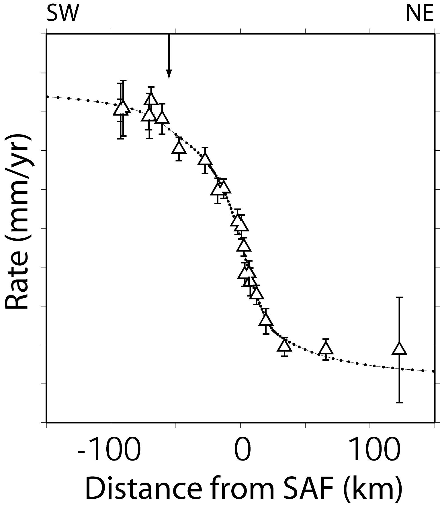
Figure 10. GPS data compared to best fit finite element model, assuming different elastic properties in the upper crust on each side of the fault. Model accounts for strike-slip movement on the Carrizo segment of the SAF (located at 0 km on the horizontal axis) as well as the Los Alamos Fault (at -59 km). The model is consistent with geologic, laboratory, paleoseismic, seismic and magnetotelluric data and is also the minimum misfit solution for the GPS data (chi2 = 9.30, reduced_chi2 = 0.58). [Schmalze et al 2006]
References
For more information on the InSAR technique, see:
Massonnet, D. and K. Feigl, Radar interferometry and its application to changes in
the Earth's surface. Rev. Geophys. 36, 441-500 (1998).
Rosen, P.A. et al.; Synthetic aperture radar interferometry. Proc. IEEE 88(3), 333-382
(2000).
Hanssen, R.F., Radar Interferometry, Kluwer Academic Publishers (2001).
References on InSAR-measured subsidence:
Massonnet, D., T. Holzer, and H. Vadon, Land subsidence cause by East Mesa geothermal
field, California, observed using SAR interferometry, Geophys. Res. Lett. 24, 901-904
(1997).
Galloway, D. L., K. W. Hudnut, S. E. Ingebritsen, S. P. Phillips, G. Pelzer, F. Rogez,
P. A. Rosen, InSAR detection of system compaction and land subsidence, Antelope Valley,
Mojave Desert, California. Water Resources Res. 34, 2573-2585 (1998).
Fielding, E. J., R. G. Blom, R. M. Goldstein, Rapid subsidence over oil fields measured
by SAR interferometry. Geophys. Res. Lett. 25, 3215-3219 (1998).
Amelung, F., D. L. Galloway, J. W. Bell, H. A. Zebker, R. J. Laczniak, Sensing the
ups ad downs of Las Vegas: InSAR reveals structural control of land subsidence and
acquifer system deformation. Geology 27, 483-486 (1999).
Bawden, G. W., W. Thatcher, R. S. Stein, K. W. Hudnut and G. Peltzer, Tectonic contraction
across Los Angeles after removal of groundwater pumping effects. Nature 412, 812-815
(2001).
Buckley, S.M., Rosen, P.A., Hensley, S. & Tapley, B.D., Land subsidence in Houston,
Texas, measured by radar interferometry and constrained by extensometers. J. Geophys.
Res.-Solid Earth 108(B11) (2003).
Tesauro, M. et al., Urban subsidence inside the city of Napoli (Italy) observed by
satellite radar interferometry. Geophys. Res. Lett 27(13): 1961-1964 (2000).
PSInSAR References:
Colesanti, C., A. Ferretti, F. Novali, C. Prati, and F. Rocca, SAR monitoring of progressive
and seasonal ground deformation using the permanent scatterers technique. IEEE Trans.
Geosci. Remote Sensing, 41(7), 1685-1701 (2003a).
Colesanti, C., A. Ferretti, C. Prati, and F. Rocca, Monitoring landslides and tectonic
motions with the permanent scatterer technique, Engineering Geol., Spec. Issue Remote
Sensing and Monitoring of Landslides, 68(1), 3-14 (2003b).
Colesanti, C. , Ferretti, A., Locatelli, R., Novali, F., Savio, G., Permanent scatterers:
precision assessment and multi-platform analysis. Int. Geosci. Remote Sensing Symp.,
Tolouse, France (2003c).
Ferretti, F., C. Prati and F. Rocca, Nonlinear subsidence rate estimation using permanent
scatterers in differential SAR Interferometry. IEEE Trans. Geoscience Remote Sensing
38(5), 2202-2212 (2000). Ferretti, C. Prati, and F. Rocca, Permanent scatterers in
SAR Interferometry. IEEE Trans. Geosci. Remote Sensing, 39(1), 8-20 (2001).
Ferretti, F., F. Novali, R. Burgmann, G. Hilley and C. Prati, InSAR Permanent Scatterer
analysis reveals ups and downs in San Francisco Bay area. EOS, 85(34), 1-3 (2004).
Troposphere Effects:
Dixon, T. H., and S. Kornreich Wolf, Some tests of wet tropospheric calibration for
the CASA UNO Global Positioning System experiment. Geophys. Res. Lett. 17, p.203-206
(1990).
Dixon, T. H., G. Gonzalez, S. Lichten and E. Katsigris, First epoch geodetic measurements
with the Global Positioning System across the northern Caribbean plate boundary zone.
J. Geophys. Res. 96, 2397-2415 (1991).